|
In this chapter, we present the grid workflow system architecture defined in the GRACCE framework. We first have a general overview of the architecture, then we discuss the three core components of the architecture. Finally, we discuss in more detail the algorithms used in workflow execution planning and resource allocations. To help present these algorithms, we simplify one term used in the last chapters. From now on, we use “task” to represent a module job; and a workflow consists of multiple tasks with dependencies.
GRACCE defines an architecture to implement a look-ahead scheduling and execution system for scientific workflow applications. The architecture addresses the issues of grid resource allocation, workflow execution and monitoring, and integrates their solutions into a middleware platform. From this platform, end users can build a custom grid environment to manage a grid application in its entire life cycle.
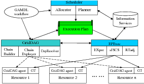
As shown in Figure 6.1, the GRACCE architecture has three subsystems, the Scheduler, the GridDAG workflow engine, and the EPExec runtime system. The Execution Plan (EP) in this architecture is a collection of the scheduling decisions for workflow tasks and the mechanisms for handling task dependencies. The EP is generated by the Scheduler in the scheduling process, and is used by the GridDAG to coordinate task dependencies. EPExec submits workflow tasks to their allocated resources and manages their execution according to the EP.
The Scheduler, with two components, the Allocator and the Planner, co-allocates resources for workflow tasks and plans the workflow execution. The Allocator discovers suitable resources, negotiates the resource provision and makes reservations with resource providers. The Planner plans workflow execution and co-allocates resources for workflow tasks. It predicts the execution scenario for each task, which is about when and how the task should be launched. The scheduling process is based upon the application workflow; the decisions made are used to create the workflow EP.
The GridDAG is an event-driven workflow coordination system. At the scheduling stage, GridDAG decides how to handle dependencies and determines the event activities that are involved in the handling. These decisions are appended to the workflow EP. During workflow execution, GridDAG coordinates the execution of dependent tasks by handling and resolving task dependencies.
The EPExec is a runtime system for workflow executions. Given a workflow EP, EPExec submits tasks to the allocated resources, and monitors the execution of these tasks. EPExec sends events related to file availability or to the status change of task execution to GridDAG for the purpose of handling task dependencies. During execution, EPExec may adjust the EP according to the real execution scenario.
An application workflow has the following life-cycle in the GRACCE architecture:
GRACCE’s Scheduler has two components, the Planner and the Allocator. The Planner predicts and identifies the execution window for each task, and the Allocator searches a list of candidate resources, negotiates and makes the necessary agreement with resource providers. A task’s execution window (EW) is a time frame during which a task is executed. EWstart denotes the EW start time, and EWlength denotes the EW length – EWlength is equal to the task wall-clock time plus a configurable buffer time. The EW of an ancestor task must be before the start-time of its dependent tasks, but the EW’s of independent tasks can overlap. In this subsection, we only give a short overview of the functionalities of the Scheduler to help understanding the whole architecture. In Section 6.2, we discuss in thorough details the scheduling process and the algorithms used.
Given a workflow, the Scheduler planning process identifies the EWs for each task using a breadth-first graph traversal algorithm. The algorithm starts with the allocation of resources for the first task of the workflow by the Allocator. When resources are allocated, the Allocator also identifies the task EW. Then, the Scheduler processes the children of the first task. First, Allocator discovers a list of candidate resources for each child task and calculates the cost of dependency handling between the resource(s) for the parent task and the candidate resources for child tasks. Secondly, the Planner predicts the task EW if it is run on the candidate resources. The EWstart is calculated by adding the EWstart and EWlength of the parent task as well as the time required for dependency handling. Thirdly, the task EW predicted for each candidate resource is processed again by the Allocator, which will allocate the best resource for the task and determine its EW. The Scheduler then moves on to process other tasks.
The Allocator allocates computational resources for workflow tasks in a sequence of resource discovery, negotiation, and reservation. During resource discovery, the Allocator queries the Grid Information Services for resources that satisfy the task resource requirements and are available during its EW. Firstly, resources are selected by a simple match-making of each attribute of a task’s specification with static resource information. The resources on which the task is able to run are further evaluated according to their runtime information. Then, the selected resources are checked for their availability during the task EW, and the Allocator finally identifies a list of candidate resources. In the negotiation and reservation stage, the Allocator requests reservations for the candidate resources during a task’s EW. If the local schedulers grant the requests, the Allocator chooses the one that can provide the earliest EW for the task. A reservation ID is returned that will be used to access the reservation later. If no reservation could be made on any of the candidates, grace periods are added to the EW and Allocator again requests reservations for other wall-clock periods within the EW until a reservation is made.
GridDAG is our event-driven workflow system; it is able to coordinate the scheduling and execution of the dependent tasks of a workflow job. Compared with other workflow enacting engines, GridDAG is a pure coordination system, without any execution or monitoring functionalities, which are provided by EPExec in GRACCE. This gives GridDAG the flexibility to integrate with various remote execution and monitoring utilities. Different coordination mechanisms can be developed in GridDAG without necessitating additional effort to integrate them with other GRACCE subsystems.
Events are notifications of a status change of task executions or file transfers, data availabilities, or other situations defined by users, such as for resource accounting purposes. An event producer detects certain situations or a status change, generates the corresponding event messages and distributes them. An event consumer receives an event message and invokes the event handlers. The GridDAG event mechanism is based on the WS-Notification standard [99], so event messages are XML documents – which allows the implementations to be platform-neutral in distributed heterogeneous environments.
Four components in GridDAG support the eventing mechanisms: the event chain builder, chain deployer, GridDAG agent, and DepResolver. The chain builder reads the job EP forwarded from the Scheduler and generates the event chains according to the EP. An event chain is an ordered sequence of events from the participating producers to consumers. The chain deployer sends subscription requests to producers. A Subscription represents the relationship between a consumer, producer, and related event messages. These relationships constitute the runtime event chains of a workflow job. GridDAG agents coordinate the runtime event activities in each grid resource. Firstly, as a producer, GridDAG agents detect events occurring on the host resources and send out event messages. Secondly, as a consumer, GridDAG agents receive event messages from other agents or EPExec and take actions accordingly. DepResolver is the overall coordinator of dependency handling and resolving. DepResolver keeps track of the states of task dependencies and decides whether all of the dependencies are resolved.
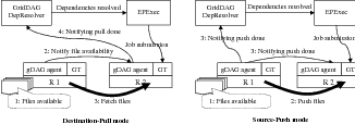
Using the GridDAG eventing mechanism to handle data dependency, file transfers can be in either destination-pull (D-P) or source-push (S-P) mode. The event sequences for these two modes are shown in Figure 6.2. In the D-P mode, when the GridDAG agent on the source resource detects that files are available (1), it sends a corresponding event to the destination GridDAG agents (2). The destination GridDAG agents fetch the files (3) and send events to DepResolver notifying it of file arrivals (4). For the S-P mode, when files are available (1), the source GridDAG agent transfers them to the destination resources (2) and sends an event to the destination GridDAG agents and to DepResolver indicating that the intermediate files have been transferred (3). We expect that the D-P mode works better when multiple destinations are waiting for the same set of data. The S-P mode is suitable for situations where data production and movement can be pipelined.
EPExec (EP Executer) is the runtime execution system for workflow jobs according to the job EP. EPExec has three components, EXEpre, sJSCS, and RTadj, to provide the functionalities of job submission, job monitoring, and the runtime adjustment of a job EP.
EPExec is implementation-independent of the Scheduler and GridDAG subsystems and communicates with them via platform-neutral event messages. This ensures it to be flexible enough to integrate with various middleware packages. Different EPExec’s can be developed to support different methods of job submission and remote execution without requiring any changes to the Scheduler and the GridDAG.
EPExec’s execution preparation (EXEpre) adds the required information for job submission and workflow control to the job EP. The details depend on the grid middleware that it is developed on. Assuming that Globus GRAM is responsible for job submission and GridDAG for workflow coordination, its work can be summarized as follows:
EPExec starts the workflow execution by submitting the job corresponding to the first task to its allocated resources according to the job EP. sJSCS (simple Job Submission and Control Service) is a utility to respond to such submission requests from EPExec. It calls the remote execution functions, such as Globus globus-job-submit to submit a single-executable job. The job is submitted using its resource reservation ID; this ensures the task is launched within its EW. A successful submission returns a global job ID, which EPExec uses for job monitoring and control.
EPExec monitors task executions in both passive-notification (P-N) mode and active-checking (A-C) mode. In the P-N mode, EPExec relies on the event messages about job status change to track the job. These messages are sent by the GridDAG agent on the resource where the job executes. In the A-C mode, EPExec calls sJSCS to query the current state of job execution. The P-N mode alleviates EPExec from the frequent calling of sJSCS; but EPExec may lose track of the job if the event mechanism fails. So normally, both the P-N and A-C modes are enabled in EPExec for a close monitoring of the job.
EPExec coordinates task executions so that the executions follow the EP. But if a task completes after its EW, the RTadj (Runtime Adjuster) component of EPExec may take actions to adjust the EP or to make up the delay. In most situations, those tasks that depend on the late task can be started within their EW’s and RTadj does not need to adjust them. But if the late completions cause the expiration of reservations of the dependent tasks and they cannot be started in their EW’s, RTadj uses the following strategy to try to make up the delay:
First, EPExec submits these tasks to their allocated resources without using reservation. The jobs may be held in the resource local queues. RTadj then requests Scheduler to discover alternative resources for these tasks. If suitable resources are discovered and allocated, EPExec submits copies of these tasks to these resources. During execution, EPExec identifies the copy that it thinks will complete first and kills the others. Thus RTadj does its best to make up for the lost time in past job execution and to minimize the negative impacts on the execution of later tasks.
If it seems impossible to follow the initial job EP, RTadj will consider re-scheduling the rest of the tasks. In this case, RTadj forwards the job sub-workflow to Scheduler to reschedule. Re-scheduling may cause low resource usage or wastage because of the cancellation of prior reservations. The Scheduler tries to avoid this situation by scheduling other jobs onto these reservations if possible.
In this section, we discuss the process and the algorithms of resource allocation and workflow execution planning, mainly the functionalities and internals of the Allocator and the Planner components of the Scheduler subsystem in the GRACCE architecture. The notations used in this section are listed in Table 6.1.
|
As we mentioned before, the GRACCE Allocator is responsible for allocating resources for a workflow task based on its resource request. The resource request specification of task Ti, denoted as ResReqTi, consists of the number of processing elements (PEs) and the minimum memory required, the start time, the optional execution time (one way to specify a deadline) and the requirements of hardware architecture and software configuration. An allocation decision, denoted as AllocResTi, consists of the resource name, the total number of PEs, a list of these PEs, the available time, the estimated execution time if the task is executed on this resource, and a reservation ID (ResvID) if it has. These two objects can be represented as follows:
ResReqTi<NumPE, minMem, StartTime, ExeTime, ArchSW>
AllocResTi<ResName, NumPEs, PEList, StartTime, ExeTime, ResvID>
The Allocator takes the resource request of the workflow task Ti, makes allocation decision and returns the decision(s) with one or more AllocResTi objects. The allocation process involves two steps, resource discovery and evaluation (Step 1), and resource negotiation and reservation (Step 2). Starting from all available resources, each step refines the results from the previous step. By the end of Step 1, one or more ResReq objects without valid ResvIDs, corresponding to one or more candidate resources, are returned. By the end of Step 2, one or more ResReq object(s) that have valid ResvID(s), corresponding to the reserved resource(s), are returned. We denote each of the two steps as AllocatorS1 and AllocatorS2 and the following formulas represent their operations:
AllocResTi[ ] = AllocatorS1(ResReqTi)
AllocResTi[ ] = AllocatorS2(AllocResTi[ ])
Resource discovery and evaluation searches in grid information services for resources that match the resource specification of a workflow task. The resources discovered by this step are those that match the requirements of hardware architecture and software configuration of the workflow task, for example, the CPU architecture, the operating system and version, the total PEs and the libraries installed on the resource. This step does not consider what Quality of Service or performance a resource can provide for the task, and it only finds the resources that are able to “execute” the task.
The grid information services are provided by the Globus Toolkit’s MDS [41]. The Globus MDS defines two key protocols: the GRid Registration Protocol (GRRP), which a resource uses to register with an aggregate directory, and the GRid Information Protocol (GRIP), which an aggregate directory or user uses to look up the status of a resource. When the Allocator starts up, it queries appropriate aggregate directory(s) to locate any potentially interesting resources. Having obtained the names and gross characteristics of these resources, the Allocator then uses GRIP to contact them directly and obtain detailed and up-to-date information.
For each of the discovered resources, the evaluation process is similar to Condor’s “matchmaking” algorithm [67], which in its basic form takes two ClassAds and evaluates one with respect to the other. A ClassAd is a set of expressions that must all evaluate to true in order for a match to succeed. Expressions in one can be evaluated using property values from the other. A ClassAd can also include a rank expression that evaluates to a numeric value representing the quality of the match. An example of a ClassAD for a grid job is shown below.
[
Type=”request”;
requirements = ”NumPE == 32 & minMem == 16G &
Arch == ’Ultra SPARC’ & opSys==’Solaris 8.0’”;
Rank= cpuSpeedPE * memSizePE;
]
In our implementation of the matchmaking algorithm, we use the same format as ClassAd to represent task specifications and resource specifications, but the algorithm is developed by ourselves that is integrated with the workflow scheduler. In operation, the Allocator first translates the task resource request specification to ClassAd and invokes the matchmaking algorithm against the ClassAds representing available resources, and returns the computed rank of this match. The rank used in the ClassAd above, the product of the average CPU speed and memory size per PE, represents the computation power of the resource. The higher the rank, the faster the resource, hence the shorter time it takes for the resource to execute the task. The discovered candidate resources are ordered using this rank value.
In the Step 1, the Allocator discovers and selects multiple candidate resources in ranked order for a workflow task; in this step, the Allocator communicates with the local schedulers of the candidate resources to finally make the resource allocation decisions for the task. As we mentioned before, the Allocator, which acts as a grid scheduler, operates on top of local schedulers that have ownership of resources. So instead of being able to directly allocate a resource, the Allocator has to request the resource from the local scheduler and the local scheduler may or may not satisfy such request. If the local scheduler denies the request, the Allocator modifies the resource request specification and resubmits the request to the local scheduler for consideration. This process is called resource negotiation and it is the process of requesting “advanced reservations” of resources from the local schedulers.
“An advanced reservation is a possibly limited or restricted delegation of a particular resource capability over a defined time interval, obtained by the requester from the resource owner through a negotiation process” [100]. An advanced reservation ensures access to specific PEs during the specified time, and it is essentially a lock on a number of PEs. Each reservation, identified by a ResvID, consists of the number of hosts/PEs reserved, a start time, an end time, and an owner. During the time the reservation is active, only users or groups associated with the reservation have access to start new jobs on the reserved hosts. The reservation is active only within the time frame specified. When it becomes active, the associated users can submit jobs that reference the reservation by the ResvID and these jobs occupy the reserved resources when being executed. Jobs occupying the reservation may be killed by the local scheduler when the reservation expires. But most local schedulers allow the jobs to keep running when the reservation expires. Advanced reservation is supported by most current local schedulers, such as SGE, LSF, PBS Pro and Maui.
|
|
The resource negotiation and reservation process is thus a two-phase handshaking between the Allocator and the resource’s local scheduler. The negotiation sequence and hand-shaking messages involved are shown in Table 6.2, and in Table 6.3, we show an example of the messages in a negotiation process. The process starts with the Allocator’s submission of a reservation request in the form of a ResvRequest message to the local scheduler. The ResvRequest consists of the number of PEs and the time period requested. The local scheduler processes this request and responds with a ResvResponse message. If the local scheduler accepts it, the message contains a “Yes” answer, a deadline within which the Allocator must confirm to finally acquire the reservation, and the reservation ID. The Allocator next replies to the local scheduler with a ResvAccept message that encodes the reservation ID. Upon receiving this message, the local scheduler responds with a ResvConfirm message that includes all the details of the reservation. From this point, the Allocator can access this reservation using the reservation ID. This process can be represented by the following two formulas:
ResvResponse = Allocator(ResName, ResvRequest)
ResvConfirm = Allocator(ResName, ResvAccept)
Workflow execution planning decides, for each workflow task, where (on which resource) and when it is launched; the Planner is responsible for performing this. To plan the workflow execution, two important parameters for each task are required, the (estimated) execution time of the task on the candidate resource and the network bandwidth between the target resources for its parent tasks and the candidate resource for the task. Performance prediction is one approach for generating these two parameters. We rely on widely used systems for this purpose, for example, application performance prediction using performance profiling [101, 102], and network bandwidth prediction using the Network Weather Service [103]. We use a Predictor to represent the prediction operations as follows:
ExeTime = Predictor(ResName, TaskSpecTi, ResReqTi)
NetworkBandwidth = Predictor(FromRes, ToRes, Time)
The Planner makes a planning decision for a workflow task based on the decisions made for its parent tasks. The planning process includes two steps: identifying the StartTime and ExeTime (the execution schedule) of the task on resources; and requesting resource advanced reservation on the resources. The planning process is shown in the following code fragment and the two steps are implemented in the two main “for” loops. For a task Ti, when the scheduling decisions for all its parent tasks have been made, the Planner starts processing it. The Planner first requests the Allocator to discover a list of candidate resources, and then evaluates each of the candidate resource by determining the StartTime and ExeTime of the task on it. To determine the StartTime, the Planner sums two time values for each of its parent tasks: the EndTime and the time required to transfer the intermediate files between the resource allocated for the parent task and the candidate resource being evaluated. To calculate the time for file transfer, the Allocator calls the Predictor to acquires the network bandwidth information on the EndTime of the parent task. The greatest sum, which is the latest time when all the input data are available, is the earliest StartTime of the task. To determine the ExeTime of the task on a candidate resource, the Planner calls the Predictor to estimate the execution time of the task based on the performance prediction approach we mentioned before. After determining the StartTime and ExeTime of the task on a resource, the Planner sorts the candidate resources using the EndTime (StartTime + ExeTime) as the key.
In the second step, the Planner calls the Allocator to request reservations on the candidate resources in the sorted order. If a reservation is granted, The Planner then requests the Allocator to confirm the reservation, thus complete the planning process for the task.
/* sortedAllocRes is a AllocRes table sorted using the endTime (startTime + exeTime).
The sortInsert function insert an AllocRes object in the endTime order. */
AllocResTi[ ] = AllocatorS1(ResReqTi);
for (i=0; i<AllocResTi[ ].size; i++) {
startTime = -1;
resName = AllocResTi[i].ResName;
for (j=0; j<ParentTi[ ].size; j++) {
pTask = ParentTi[j];
EndTimepTask = StartTimepTask + ExeTimepTask;
bd = Predictor(AllocRespTask.ResName, AllocResTi[i].ResName, EndTimepTask);
eStartTime = EndTimepTask + FileSizepTask:Ti / bd; #estimated start time
if (eStartTime > startTime) startTime = eStartTime;
}
exeTime = Predictor(resName, TaskSpecTi, ResReqTi);
AllocResTi[i].StartTime = startTime;
AllocResTi[i].ExeTime = exeTime;
eEndTime = startTime + exeTime;
sortInsert(sortedAllocRes, eEndTime, AllocResTi[i]);
}
AllocResTi = sortedAllocRes; # now it is sorted based on the QoS
for (i=0; i<AllocResTi[ ].size; i++) {
Msg(ResvRequest) = <AllocResTi[i].NumPEs, AllocRescTask[i].StartTime,
AllocRescTask[i].StartTime + AllocRescTask[i].ExeTime>;
resName = AllocResTi[i].ResName;
Msg(ResvResponse) = Allocator(resName, ResvRequest);
if (ResvResponse.YES/NO == “YES”) {
Msg(ResvConfirm) = Allocator(ResvAccept<resName, ResvResponse.ResvID>);
AllocResTi[i].ResvID = ResvConfirm.ResvID;
break;
}
}
The algorithm above is the core of the workflow planning policy. For a whole workflow planning, the planning algorithm performs a breadth-first retrieval of the workflow DAG starting from the starting task(s), and processes the workflow tasks in the topologically sorted order. Depending on how deep the planning process retrieves the workflow DAG, the algorithm can be classified into three categories: full workflow planning, just-in-time planning(scheduling), and partial workflow planning.
In full workflow planning, the algorithm processes the workflow tasks from the starting tasks till the end tasks, and makes scheduling decisions for all tasks. The advantage of this approach is that it allows the resource reservations to be requested much earlier than the StartTime, thus increasing the possibility of being granted, even in heavily-load environments. But using this policy, the ExeTime of each workflow task must be provided or can be estimated (accurately). The accuracy of the task ExeTime greatly impacts the quality of the planning. The inaccuracy of the estimated ExeTime is propagated in the planning process along with the workflow DAG retrieval; low quality or even unworkable planning schedule may be produced. So this approach is suitable only for workflows that have predictable and accurate ExeTime for each task and it is the best approach for scheduling workflows with deadlines in heavily-loaded environments.
In this policy, the Planner discovers and allocates resources for a workflow task only when the executions of all its parent tasks complete. The advantage of this policy is that the StartTime that is calculated based on the EndTimes of the parent tasks is much more accurate than that in a full or partial workflow planning because this EndTime is not an estimated time value, but the real EndTime of the parent task. The inaccuracy in, or the inability of calculating, the ExeTime of the task would not impact the quality of planning for later tasks. The disadvantage of this policy is that the Planner may not acquire a resource reservation because the time between when the reservation is requested and when the reservation is activated is too short, which is the time for transferring the immediate files. The Planner finds a resource that has the shortest queue waiting time and queues up the task in the resource’s local scheduler. In heavily-loaded environments, this waiting may delay the whole workflow execution dramatically. So this approach is suitable for lightly load environments or workflows that do not have strict deadlines. For workflows that do not have enough information for the Planner to predict the ExeTime of each task, the Planner has to use this policy.
In this policy, the depth of workflow DAG retrieval during the planning process is between the other two policies. The Planner makes scheduling decisions for a subset of the workflow tasks starting from the starting task(s), and then launches those tasks according to the schedules that have been made. Near or upon the completion of those tasks, the Planner makes scheduling decisions for the next subset of the workflow tasks based on the information about the completed tasks. This iteration continues until all the workflow tasks are completed. This policy is very suitable for deep workflows that have large number of tasks, and the negative impacts of the disadvantages of the other two policies on the planning quality can be alleviated if the task subset is chosen properly.
As a summary of this section, we note that the three scheduling policies require two supports from the underlying local schedulers and other middlewares. First, the resource advanced reservation support should be available and enabled in the local scheduler. This feature can always be exploited by the three policies to reduce queue waiting time. But the full or partial workflow planning policy requires it to be available in order to make the best-effort execution planning. If this feature is not available, we recommend using just-in-time scheduling policy instead. Second, middlewares that provide the functionality of performance prediction of task execution time on a resource should be available. This is required by the workflow scheduler in order to make the resource allocation decisions in advance in full and partial workflow planning policies. As we mentioned, the accuracy of the prediction impacts the quality of scheduling and planning. So if the performance of an application is not predictable, or the prediction is not accurate enough, only the just-in-time scheduling policy can be applied. If those applications have regular executions, a common approach in scheduling would be to apply the just-in-time scheduling policy first, and then gather the execution history for each of its executions. Based on this historical information, the scheduler makes predictions of its future executions, and compares the predictions with the real execution scenarios to see how accurate these predictions are. If the predictions become accurate enough to make good workflow planning, the full or partial workflow planning policy can be applied. This is a topic of machine learning that can be explored in order to improve the performance of applications using our scheduling policies.
In this chapter, we presented our grid workflow system architecture and the algorithms of workflow resource allocation and execution planning in the GRACCE project. The project aims to provide an end-to-end solution for automatic workflow execution in grid environments. Using the GRACCE middleware, domain scientists are only required to specify the application logic and resource requirements; GRACCE is responsible for allocating grid resources for the application workflow, for launching the workflow, and for the delivery of the results back to the users.
The GRACCE workflow system architecture provides and integrates solutions to grid scheduling related problems. The three subsystems in the architecture, the Scheduler, the GridDAG workflow engine, and the EPExec runtime system, constitute an extensible platform for the integration of grid middleware and applications. Grid middleware solutions can be easily interfaced with one of the subsystems without changing the other subsystems. From this platform, end users without any in-depth grid knowledge are able to deploy their applications on the grid easily.
The GRACCE scheduling algorithms apply advanced scheduling techniques, such as look-ahead resource co-allocation, execution planning and performance prediction, during the workflow resource allocation and scheduling process. By taking into account the various factors that may impact the workflow execution performance, such as the dependency relationships of workflow tasks, the network bandwidth and intermediate file size between dependent tasks, the GRACCE scheduler makes scheduling decisions with the goal of improving the overall workflow performance, instead of individual task performance. We believe by applying those techniques aggressively, the users’ expectations of quality of services, such as workflow execution time, can be easily met.