|
|
In this chapter, we present the high-level abstract language we developed for grid workflow application description, the Grid Application Modeling and Description Language (GAMDL).
GAMDL was designed to address the major limitation of current workflow description languages in support for resource allocation for workflow tasks. It is feature-rich, and is more powerful and flexible than those related efforts we have studied in the last chapter. We summarize the capabilities and features of GAMDL as follows:
GAMDL is XML language-based and the GAMDL syntax is developed as a set of XML-Schema [97]. XML is the most widely used modeling language for workflow description in grid computing and has a very rich set of development tools. XML-Schema is used to define a set of rules to which an XML document must conform in order to be considered “valid”. As a W3C standard, it provides a rich data model that allows us to express sophisticated structures and constraints used in GAMDL. The use of XML-Schema for GAMDL helps us easily develop a GAMDL parser using the open source XML development library, Apache XMLBeans [98]. XMLBeans binds XML data with Java objects through the schema of the data expressed in XML-Schema. In our example, after we have designed the GAMDL XML-Schema, the XMLBeans compiler takes the GAMDL schema and generates Java codes that access a GAMDL document. All the data types, XML documents and elements in GAMDL are mapped to Java classes. Using these automatically generated codes, we can easily develop a GAMDL parser in pure Java language.
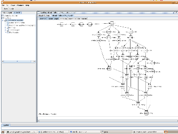
A simple GUI interface, GRACCE Appdesc that can display a GAMDL workflow as graph, is developed. In Figure 5.1, we show a snapshot of its interface. The Appdesc is also the interface of our workflow system. From the Appdesc, users can load a GAMDL application and workflows from XML documents, schedule them and monitor their executions using the workflow graph. We refer interested readers to the GRACCE website [92] for more information.
GAMDL is a data-flow style language, and the description of a workflow application includes the specification of the application entities and the specification of the relationships and dependencies between entities. In this section, we discuss the main entities used in GAMDL.
In distributed and heterogeneous environments, a computational job is often specified in
an abstract, platform-independent format by users and runtime systems translate the
specification to a platform-dependent launching script that is used to create the execution
instance. The main issue in developing a specification language for different level of
users and runtime is how to flexibly define the properties of an execution to
such an extent that different levels of users can specify them in the abstraction
level only they need. To support such flexibility, GAMDL splits an execution
specification into two parts, the execution schedule and the execution configuration. An
execution schedule includes information about when and where the executable is
launched, such as its start time and host name. An execution configuration includes
information about how the executable is launched, such as its launcher (e.g., a
bash shell), directory, arguments and environment variables. In this separation,
the platform-independent information in the execution configuration is supplied
by users. When the scheduler allocates a resource for the execution, it fills in
the execution schedule. Based on the architecture of the allocated resource, the
runtime system fills in the platform-dependent part of the execution configuration.
Another field that is part of an execution specification is the resource request. The
resource request lists the resource details required for this execution, such as the
number of CPU and the memory size. Based on this information, the scheduler
makes resource allocation decisions and generates an execution schedule. An
execution is of ExeType type in GAMDL schema, as shown in the following code
fragment.
In the ExeType schema, most of the fields (elements or attributes in XML terms), such as executable and location elements, are self-explanatory. The execution schedule is specified in the exeSchedule field of ExeScheduleType type, the execution configuration in the exeConfig field of ExeConfigType type and the resource request in the resrcReq field of ResourceReqType type.
The code fragment above shows the schemas of ExeScheduleType and ResourceReqType. The retry field in ExeScheduleType is used to specify how the system should rerun this schedule if the last execution fails. The retry string is defined in format of “[Integer]:[Integer]:[Integer][+|x|e]”. The first integer is the maximum number of retries; the second one is the first interval (in second) and the base to calculate the interval between each retry; The last [Integer][+|x|e] is used to define how the interval is calculated in each retry, e.g., 4+ means the next interval is the current one plus 4; 2x means the next interval is 2 times the current one; 2e means that next interval is the current one powered by 2. For example, “retry=“5:2:2x”” means that the scheduler should retry this execution up to 5 times if the first one fails, and the intervals between each try, in seconds, are 2, 4, 8, 16, 32.
In the ExeConfigType type, the six fields of ScriptType type are used to specify the application-specific scripts for different purposes. The validator script is used to check whether a completed execution generates the expected results or not; for example, whether the data in the output files are correct or not. While the execution’s exit code from the operating system tells whether it has completed or failed, the use of the validator script allows users to validate the execution using application-specific methods or algorithms. The preprocesser script and the postprocesser script are launched before the executable is launched and after the execution is complete. The cleaner script is used to clean out the temporary files after execution. The killer is the script used to kill the execution process and its child processes if it has any. This is very useful for terminating all the processes of an MPI program. The doctor script is used to check the health of the execution and it is often called by the run time system.
Using these six scripts and the retry feature mentioned before, users can design robust and automated failure detection and restart functions for an execution. For example, if a parallel MPI application runs much longer than its past executions, it is very likely that the application’s parallel processes have lost the state of internal communications and it hangs forever. The runtime system detects this using the provided doctor script and kills the hanging processes using the killer script. It then validates whether the expected results are generated using the validator script because the application may have lost communication state at the end of the execution, e.g., when closing the communication sockets after all the application data are generated. If it is a failed execution, the runtime system invokes the cleaner script to clean the temporary and incomplete output. According to the retry pattern configured in the retry string, the runtime system restarts the execution. These features are requested by a group of application users [93] and are very useful for applications that run frequently, e.g., daily. Users do not need to intervene very often to deal with those errors that can be recovered from by the system.
The core entity in GAMDL for describing a workflow application is “module”. A module is an application component to accomplish certain application goals, typically, processing input files and generating the required output files. A module is associated with one or more jobs and their executions are all able to accomplish the module’s goals. A common case of having multiple jobs is when the module code has been compiled into several binaries for different platforms. Each of these binaries can be specified in one job. A module may have multiple input and output files. All the module jobs should consume these same input files and generate the same output files. The schema of the GAMDL module, the ModuleType, is shown in the following.
The inputFiles and the outputFiles fields in the schema are self-explanatory. The jobSpec and the metaJobSpec fields are for specifying the two types of GAMDL module jobs, the regular job and the meta-job. A regular job is a single execution and it is of ModuleJobSpecType type. A meta-job, of MetaJobSpecType type, is a workflow. The use of a meta-job allows the construction of nested workflows where a workflow contains another workflow. In a MetaJobSpecType-typed meta-job, the workflow is specified by the appRun field of AppRunType type. We shall discuss this schema later on. The schemas for the two types of jobs are shown in the following.
In the ModuleJobType schema, the exeSpecUid attribute references an ExeType-typed execution that is already defined. The three elements, the exeSchedule, the exeConfig and the resrcReq, are for specifying the job-specific execution details and resource request. Although the execution specification referenced by the exeSpecUid attribute also provides these, allowing them to be provided here gives users the option of supplying module-specific details for an execution, and allows them to customize an execution in one module without changing the execution itself. For the same reason, the dftExeConfig, dftExeSchedule and dftResrcReq fields in the ModuleType schema are for specifying the corresponding default for jobs. If a field is not given in the job specification, the corresponding default is used. Also, since a module may belong to one or more applications or workflows, these fields may be given in the application and workflow description, too, in order to provide custom execution details specifically for that application or the workflow.
Finally, we note that both regular and meta module jobs can be identified via an index, the index field of the above schemas. An index is a sequence number that orders the job specifications. The dftJobIndex field in the ModuleType schema tells the scheduler which job should be considered first when allocating resources.
In applications, such as AQF, multiple modules use the same executable with different, but similar execution details and input/output files. For example, there are 6 different CMAQ modules in the AQF workflow shown in Figure 4.1 for forecasting air quality in three domains and for two days. The differences in the use of the six modules are in the specification of the execution configuration and input/output file names. To describe them one by one is tedious work. Moreover, changes in the specification of the CMAQ execution may requires changes in that of all the six CMAQ modules. This has proved to be an error-prone editing process and the readability of the resulting description is poor. We have introduced additional language support for these to improve the usability and readability of workflow specifications. These new features in GAMDL are provided via the “multi-value property” and the “entity unique id”.
A Multi-value property (mvproperty), as its name implies, is a property that may have multiple values. It is defined as mvpName = {v0,v1,...,vn}, and is referenced by $mvpName. #mvpName denotes the number of values defined. A reference to mvpName replicates the referencing sentence #mvpName times; in each replica, the reference is replaced with a distinct one of its values. For example, if we define dmsz = {36k, 12k, 4k}, and day = {d1,d2}, the sentence aqf-mm5-${dmsz}-${day} represents all six instances (#dmsz * #day) of the AQF MM5 modules in Figure 4.1. In an XML document, the replication of an mvproperty reference is on an element basis. When the GAMDL parser encounters a reference to an mvproperty, it replicates the nearest outer element that contains the reference. This element is called the containing element of the mvproperty reference. The parser does not recursively process the same references in the child element of the containing element; instead, it instantiates all references to the mvproperty in a replicate element with the same value.
In the GAMDL description for the AQF application, the mvproperties are defined as follows:
The following code fragment describes the six CMAQ modules in Figure 4.1 using these mvproperties.
The entity unique id (uid) is an attribute to uniquely identify an entity, for example a job or a module, as shown in their schemas presented above. It is provided by users when specifying an entity. To include a defined entity in another entity’s specification, the user only needs to reference it by its uid. In the code fragment above for CMAQ module definition, the module uid is defined to be “cmaq-${dmsz}-${day}” which covers the six modules. The input/output files are specified by the uid references of the corresponding files. This is the typical usage of uids in GAMDL, that is, the application entities are defined in several documents, one for each type of entity; and the documents for specifying entity relationships and workflows use these entities via their uid reference. In this way, changes in the entity specification do not necessitate changes in the documents for higher-level application specification. It enables the creation of well-organized document structures that match human approaches to organizing this information. The use of uids also enables the re-use defined entities in other applications; it can be used as the key or foreign key reference when storing an entity in an RDBMS or XML database.
GAMDL models a domain problem as an application and an execution of the application as a workflow. It allows both data-flow and control-flow logics to be described using data-flow style syntax.
In GAMDL, application and workflow are two different concepts. An application is a high-level model of a domain problem from the viewpoint of an end user; a workflow is an execution instance of the application. An application definition includes the specifications of all the application entities and of the entity relationships and dependencies. A workflow definition specifies which application entities are included in the workflow execution and with which module(s) the execution starts; the runtime workflow is then constructed based on the high-level application specification. One advantage of this separation is that it allows users to specify multiple and different workflows of an application based on their needs without defining a new application each time. The support for subworkflow and partial workflow is thus provided naturally from this separation. A GAMDL application is defined in an application document and a GAMDL workflow in an appRun document. The structure of the application document is illustrated in the following code fragment.
As this code fragment demonstrates, the collection of the definition of all application entities is via uid references. These references are organized in three child elements, appExes, appDataFiles, and appModules, each for one of the three types of application entities respectively, i.e., execution, file, and module. The descriptions of module relationships and dependencies are in the appMdRships element: we discuss its details below. The next code fragment shows the AppRunType schema for the appRun document.
In the workflow schema, the application specification is referenced via the appUid attribute. The startTime string states when the workflow should be launched: it allows a sophisticated cron job format for reoccurring executions of the workflow. The mdRun element of MdInAppRunType type is for specifying the inclusion of application modules. It includes the module uid reference, the job index of the module, the execution details, i.e., the execution configuration and the execution schedule, and the resource request. This schema allows users to provide workflow-specific execution details and a module job index. As the ModuleType schema, the three elements, dftMdJobResrcReq, dftMdJobExeConfig and dftMdJobExeSchedule, are used to specify the default values of resource request and execution details of the workflow modules. These default values are used for a module whenever its mdRun element does not provide them. Lastly, the starting module(s) of the workflow are specified in the startMd element as uid references to the workflow modules. The following code fragment is an example of an AQF workflow definition.
In the workflow specification, users do not need to specify the module relationships and dependencies. They are all given in the appMdRships element of the application document. In the following two subsections, we explain how data-flow and control-flow logics are described in GAMDL.
GAMDL models the application data-flow as a DAG, and captures both the dependency relationships between modules and the intermediate files associated with these relationships. A dependency relationship can be defined in either parent-children (PCn) pattern or child-parents (CPs) pattern. A PCn relationship, specified as a PCnRship element in GAMDL, has a parent module and one or more child modules, and a CPs relationship, as a GAMDL CPsRship element, has a child module and one or more parent modules. Intermediate files in a relationship are specified as pipes, one file per pipe. A pipe has a pipeIn element and a pipeOut element; the pipeIn element represents the piped output file of the parent module, and the pipeOut element the piped input file of the child module. The next code fragment is part of the appMdRships element in the AQF application document. It describes the PCn relationships between the SMOKE and CMAQ modules, and between the CMAQ modules for the first day and the second day forecasting of the AQF application in Figure 4.1.
GAMDL allows the specification of control-flow logics, such as loops or conditional branches, by introducing conditional pipes and variables. A conditional pipe associates a pipe with a Boolean if condition which will be evaluated after the module completes execution. If it evaluates to true, the pipe is processed; otherwise, it is not. If the conditions of all pipes in a relationship are evaluated to false, runtime dependency is not established and the child module will not be executed. A GAMDL variable is a <name, value> pair associated with an if condition. A new value can only be assigned to the variable if the associated if condition evaluates to true; if no if condition is specified, an assignment is always made. If the value being assigned is in the form of value1:value2, value1 is assigned if the if condition is true and value2 is assigned otherwise.
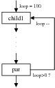
In GAMDL, complex flow controls are achieved by the proper assignment of variable values and reasoning on the conditions associated with pipes and variables. The run time system can assign values to variables before a module’s execution (in a preAssign element) and/or after a module’s execution (in a postAssign element). The condition associated with a variable assignment or a pipe is permitted to reference system environment variables as well as GAMDL variables defined in other modules. In the following for loop example, the child1 module postAssigns 100 to the loop index (loop) if the loop variable has not yet been defined (which means this iteration is entering the loop), or ${loop} - 1 in each subsequent iteration. In the pCnRship of par module and child1 module, a null pipe (using /dev/null file) is specified with an if condition as ${loop}> 0. In each iteration, if the condition evaluates to ”true”, the pipe is established and control passes to the child1 module.
|
In Section 5.5, we give a more detailed example showing how a workflow with loops and conditional branches is specified using conditional pipes and variables. We want to note here that the control-flow specification introduces additional complexity in reasoning about the module execution order, and is best used for the specification of simple control-flow logics.
GAMDL introduces the specification of two types of information about a module to aid a workflow scheduler when it is making resource allocation decisions; the resource request information of a module or workflow job, and the historical and profiling information about a job’s execution on a resource.
As we mentioned before, the resource request of an execution is specified using the ResourceReqType type, shown below. It lists the resource details required by the execution. Two attributes we want to note here are the host and hostCPUList. These two fields are optional. If they are specified, it tells the scheduler that dedicated resources are requested; otherwise, the scheduler allocates resources for the execution and fills in these two fields. This allows users to manually allocate resources for some workflow tasks and specify them in the execution specification. Using those dedicated allocations as hints, the workflow scheduler can make much better decisions for tasks for which users do not specify dedicated resources.
GAMDL associates the resource specification with a workflow module, which provides a natural solution for specifying resource multi-requests according to the workflow. When allocating resources for module jobs, a scheduler makes resource allocation decisions based on the module dependency relationships, for example, sibling module jobs are allocated concurrent resources if possible. The scheduling process is thus orchestrated by the workflow. Under Globus RSL [77], users have to explicitly specify the resource multi-requests for the purpose of resource co-allocation [39, 82]. These resource multi-requests have to be constructed manually according to the dependency relationships of the workflow modules. While it would be possible to associate the RSL of module jobs with the workflow, the ability to specify resource multi-requests in RSL is then lost.
The Execution Profiles of a module job in GAMDL are the historical and profiling information about the job executions on different grid resources. They provide the scheduler the historical information on observed executions in order to predict its future execution. For applications like AQF that run every day under similar scenarios, it is very easy to predict the execution of a module job on the resource on which it has been executing. Based on such prediction, the scheduler can make much better resource co-allocation decisions for module jobs. Also statistical analysis, data normalization and scaling may be performed on the historical data for other purposes, such as improving resource usage.
The GAMDL schema for a job execution profile is ExeProfileType, shown in the following. GAMDL organizes the execution profiles of a module job based on the resources the job has run on, with one profile for each resource. A module job may have been executed several times on a resource; each execution is described as an execution scenario, consisting of a list of the resources consumed, of ExeScenarioType type. In each profile, scaling algorithms are defined to calculate the possible resource usage based on the available scenarios.
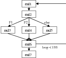
In this section, we use a workflow example in Figure 5.2 to show how complex control-flow logic, such as loops and conditional branches, is described in GAMDL. In the example workflow, the module md2 generates different output files (F1, F2 or others) in different loops, and these files are processed by module md3, md4 or md5, respectively. The loop count is 100.
In the GAMDL description shown below, module md1 postAssigns a loop variable, whose initial value is 100 and stride is -1. The module md2 postAssigns two variables, F1recent and F2recent. F1recent is set to true if file F1 is generated by md2 in the last execution, otherwise F1recent is set to false; F2recent is handled similarly with respect to file F2. The pipe condition for md3-md2 CPsRship is set to “pipe(F1) && ${F1recent}”, which is evaluated to true if F1 is generated in the last execution and is available for piping in. The if conditions for the F2 pipe in md4-md2 CPsRship and the else-pipe in md5-md2 CPsRship are similar to the F1 pipe. Loop control is specified in md1-md6 CPsRship of md1 and md6 using a null pipe with condition “${loop}<100 ”.
In this example, GAMDL uses condition functions, such as generated(F1), in a condition string. A condition function is a regular function (binary or script) that returns a Boolean value; it should not make any modification to its externals. In the following specification, the pipe(fileName) function checks whether a file can be piped in or not. The generated(fileName) function checks whether the module execution generates the specified file; the defined(variableName) function checks whether a variable is defined or not.
In this chapter, we presented the Grid Application Modeling and Description Language (GAMDL), a high level abstract language for domain users to describe a workflow application. GAMDL, designed to address the limitations of current workflow languages with respect to support for resource co-allocations for workflow tasks, is feature rich. It associates resource request specification and execution profile with workflow module specification, so resource multi-requests can be easily constructed by software based on the workflow. The execution details of a workflow job can be specified in different contexts, thus providing a flexible means to organize and reuse the entities in different applications without having to redefine them. Using GAMDL, both data-flow and control-flow relationships can be described using DAG style structures. Users do not need to manually construct the application’s control-flow if they have a data-flow application. Other features of GAMDL include the use of mvproperties to describe similar entities, and its support for nested and partial workflow.