|
In this chapter, we introduce scientific workflow applications and how this type of application is specified and scheduled in computational grid environments.
Grid scientific modeling and simulation, such as environment and earth science research [5, 56, 57], automobile collision simulation [58], space and astronomy exploratory [59], and physics collision experimentation [60, 4], are applications that make intensive use of numerical tools, require high compute power for the simulation and visualization, and entail transfer, storage and analysis of a huge amount of data. A simulation of these problems incorporates multiple dependent modules to be executed in predefined order on multiple computational resources. An uninterrupted simulation requires transfer and storage of the module data between the execution resources in a timely manner. These applications are often referred to as scientific workflow applications [61].
A workflow can be defined as a collection of processing steps (also termed as tasks or modules), and the orders of task invocation or conditions(s) under which task must be invoked and/or the data-flow between these tasks. The execution order of two tasks forms a dependency relationship between them, and the two tasks are referred to as the parent task and the child task. A parent task must be completed before its child tasks start and the child task is executed using or based on the output of its parent tasks. Tasks without dependency relationships are referred to as sibling tasks. The relationships of the inter-dependent tasks are either data-dependencies, as of files between dependent tasks, or control flow, such as loops or conditional branches.
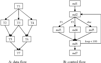
Figure 3.1 shows the graph representations of two workflows: a rectangle represents a workflow task or module, and an arrow represents the dependency relationship between the connected tasks. The workflow of Figure 3.1:A has only data dependencies. Each of the tasks, T1 to T7, processes and produces data and the output of a task are used by its child tasks. The data dependencies are pre-defined in advance, thus determining the execution order of these tasks. We often refer to this type of workflow as static workflow, or data flow.
A workflow with control dependencies are referred to as dynamic workflow, or control flow. In this type of workflow, some dependency relationships are only established during workflow execution. For example, in the workflow of Figure 3.1:B, the module md2 generates one of the three files, F1, F2 or F3, in different loops. The three files are processed by module md3, md4 or md5, respectively. The loop count is 100. The dependency relationship between task md2 and md3 is established only when md2 generates file F1. Scheduling dynamic workflows is much more complex than scheduling a static workflow because of the complexity in allocating resources for uncertain task relationships in advance. Also based on the fact that most of the scientific applications are for data processing and visualization that can be specified as static workflows, we focus our research on static workflows at this stage.
To execute a workflow, a user provides a workflow specification describing the required tasks and their dependency details, and submits this specification to a workflow scheduler for execution. The scheduler allocates resources for each of the workflow tasks and launches the tasks in the workflow-defined order. During the workflow execution, the scheduler is responsible for handling task dependencies, such as transferring the dependent files, and for launching tasks when their dependencies are resolved. The system for specifying and scheduling workflows is often called a workflow management system.
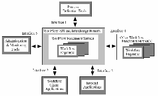
The Workflow Management Coalition (WfMC) is an international organization to promote and develop the use of workflow through the establishment of standards for software terminology, interoperability and connectivity between workflow products [62]. The WfMC defines a workflow management system as “a system that completely defines, manages, and executes workflows through the execution of software whose order of execution is driven by a computer representation of the workflow logic” [63]. With this definition, WfMC also defines a reference model for the architecture of a workflow system, as shown in Figure 3.2. The reference model describes the major components and interfaces within a workflow architecture. The two core components of any workflow system are the workflow enactment service, also termed as workflow engine, and the workflow process definition tools, often referred to as workflow description or modeling tools in literatures of grid computing. We refer readers to [63] for the details of this model and the discussion of the two core components in the context of grid computing are as follows.
Workflow description is the basis of the establishment and execution of grid workflows and provides a meta-model to describe physical processes. The widely-used methods for workflow description are the workflow description language and the GUI graphical specification. A workflow description language defines standard syntax and semantics for specifying workflow tasks and their relationships; thus it provides an abstract and formalized representation of the complex workflow structures in text format. In GUI graphical specification method, the definition or inclusion of tasks is by mouse click or drag-and-drop; and the definition of control flow and data flow between tasks is accomplished by connecting task icons with specialized arrows specifying the control dependencies or data dependencies. Although intuitive and easy-to-use for end users, the drag-drop graphical interface method still relies on a description language to represent the workflow internally. So it is considered as a user interface of a workflow language, and in most cases, it is less powerful than the language itself. In developing a workflow system, a graphical interface is developed after finalizing the definition of the workflow language itself.
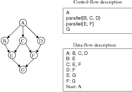
There are mainly two styles to define a workflow language, control-flow style and data-flow style. In control-flow style, the execution order of workflow tasks are specified explicitly. It is either in the order of specification statements or specified using imperative-programming syntax, such as, “if”, “while”, “sequential”, “parallel”, “fork” and “join”. For example, in the control-flow description of the workflow of Figure 3.3, the task execution order is {A, parallel{B, C, D}, parallel{E, F}, G}; and the parallel{B, C, D} means that task B, C, and D can be executed in parallel, but they are all after task A. The formalized model for control-flow style is the Petri Net [64], and in [65, 66], the authors show how Petri Nets are used for workflow description.
Using data-flow style in a workflow description language, the workflow consists of a set of tasks, one or more start tasks, and a set of dependency relationships. The dependency relationships determine the execution order of the workflow tasks. Data-flow description is the Directed Acyclic Graph (DAG) representation of the workflow and it is able to specify most of the current scientific workflow applications. Compared to the control-flow style, only dependency relationships between relevant tasks need to be specified, as shown in Figure 3.3. For big workflows, the control-flow style makes it very complex and error-prone for users to reason about the sequential or parallel execution orders of the tasks. But using data-flow style, the task execution order can be easily determined by the workflow scheduler based on the task dependency relationships. So the DAG-based data-flow style is a much easier method for users to describe static workflow than the Petri Net-based control-flow style.
A workflow language that allows users to specify the control flow and data flow among tasks by itself is not enough. In grid environments, there is a need for a language to provide information to the workflow scheduler to help the resource allocation decision-making process. The workflow task specification should provide resource request information of the task execution, and/or scheduling hints such as past execution information, as well as the details of how to launch the task. The workflow scheduler uses such information to discover and select suitable resources for the workflow task.
The workflow scheduler, also termed as workflow enact engine, provides a run-time environment that executes the workflow tasks and coordinates the task execution and dependency handling to make sure they are processed in the right order. It can be as simple as performing a topological sort [6], and then launches the workflow tasks according to the topological order. In computational grid environments, this issue becomes much more complex than it appears to be. For example, we must allocate multiple resources to workflow tasks according to the task dependency relationships and reduce the queue waiting time for the tasks that are submitted to resources for execution. So a grid workflow scheduler should have at least two capabilities: first, resource allocation, which distributes tasks onto multiple resources, and second, task execution and coordination, which submits tasks to the resource’s local schedulers in the right order, and handles task dependencies. In a DAG workflow, the task dependencies determine the order of task submission, which is the topological order of the workflow DAG. In this order, the earliest start-time of each task can be calculated easily, as long as we know when the workflow itself should be started. Since the launching time of each task is determined by the workflow dependency relationships and the workflow launching time, workflow scheduling is mainly concerned with how to allocate resources for each task according to the task execution order. A resource should be allocated to a task right after its dependencies are resolved and no delay should be incurred because of the unavailability of resources.
There are two strategies for allocating resources for workflow tasks in a workflow scheduler: just-in-time allocation and look-ahead allocation. In the former, the scheduler discovers resources and makes allocation decisions for a task when its dependencies are resolved. But it may face situations, especially in high-load grid environments, when no resource is available for a ready task. Workflow execution has to be put on hold, while the scheduler continues to search for a resource.
In look-ahead allocation, the scheduler plans the execution of all or a subset of tasks and makes allocation decisions for them in advance. When a resource is allocated for a task, the scheduler is confident or can guarantee that the resource will be available. So there are no, or only short, delays waiting for resources to be available when a task is ready, even in high-load environments. The planning process requires the prediction of both workflow execution and resource availabilities. It involves resource discovery, negotiation and reservation for the workflow tasks.
A workflow execution requires multiple resources to be simultaneously available in order to deliver the best performance. For example, tasks without dependencies should be scheduled on different resources for concurrent execution; tasks with data dependency should be allocated on the same resource to save data transfer cost. A scheduler should be able to co-allocate these resources based on the workflow dependency relationships. Grid resource co-allocation involves resources across different administrative domains that have different allocation policies. As we mentioned before, a grid scheduler does not have control over the resources and requests resources via the local schedulers. A workflow scheduler in computational grids should have the ability of coordinating resource requests from different local schedulers with regards to the workflow task relationships and an allocation decision made should minimize the unnecessary delays in execution due to the unavailability of resources for ready tasks.
In a single computing system, such as a cluster, which normally has shared file systems and high-speed interconnection between nodes, resources being managed are mainly CPUs and memory, and the local scheduler does not need to consider the impacts of network bandwidth and data size on the application performance. A resource allocation decision is purely about how many CPUs, and on which nodes, should be allocated for a particular job. In a grid environment, a workflow task requires input/output data to be staged-in/out from/to different locations connected by the Internet that does not guarantee network bandwidth. The time spent on data transfer may become a significant part of the task round time if a huge amount of data is transferred on a slow network. When choosing computational resources for the workflow tasks, a grid scheduler should mediate the time for data transfer compared with the task execution time; and should also check whether the candidate resources have enough storage space for the input and output data. So compared with a local scheduler, a grid scheduler must be data and network aware and takes the network bandwidth and workflow data size into consideration in making resource allocation decisions.